ESP32-P4 Smart 86 Box
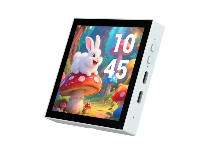
ESP32-P4 Smart 86 Box features 4-inch square touch display for Smart Home and IIoT applications Designed for Smart Home or industrial IoT (IIoT) applications, Waveshare’s ESP32-P4 Smart 86 Box is equipped with a 4-inch square touchscreen display, an ESP32-C6 module with WiFi 6 and Bluetooth connectivity, and a range of connectors. Two models are offered: the ESP32-P4-WIFI6-Touch-LCD-4B with a MIPI CSI camera connector and a 28-pin GPIO header, and the ESP32-P4-86-Panel-ETH-2RO with a bottom board that features an RS485 serial interface, two relays, a 10/100Mbps Ethernet RJ45 connector, and 6V-30V DC input. ESP32-P4 Smart 86 Box ESP32-P4-WIFI6-Touch-LCD-4B model ESP32-P4 Smart 86 Box specifications: Main module – ESP32-P4-Core Module Microcontroller – ESP32-P4NRW32 MCU Dual-core RISC-V microcontroller @ 400 MHz with AI instructions extension and single-precision FPU Single-RISC-V LP (Low-power) MCU core @ up to 40 MHz GPU – 2D Pixel Processing Accelerator (PPA) VPU – H.264 and JPE...